How does the dissolved gas analysis of transformer oil samples?

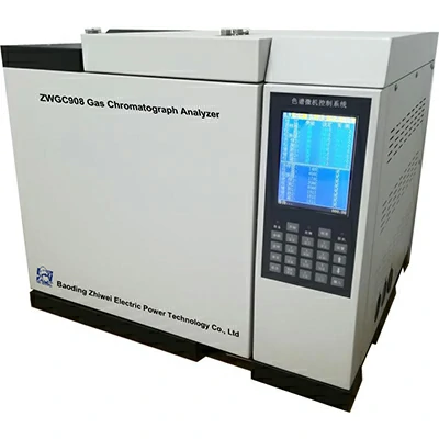
Dissolved Gas Analysis (DGA) of transformer oil samples is a diagnostic technique used to assess the condition of power transformers and detect potential faults or abnormalities.

Here’s how the process typically works:

  1. Sample Collection: A representative sample of the transformer oil is collected from the transformer’s oil reservoir. This sample is usually obtained using dedicated sampling equipment and procedures to ensure accuracy and reliability.
  2. Sample Preparation: The collected oil sample may undergo various preparation steps depending on the DGA method used and the requirements of the laboratory. These steps may include filtration to remove solid particles, degassing to remove dissolved gases, and temperature stabilization to ensure uniformity.
  3. Gas Extraction: The dissolved gases present in the transformer oil are extracted using a suitable method, such as headspace extraction, membrane separation, or vacuum degassing. This process allows the gases dissolved in the oil to be transferred to a gas phase for analysis.
  4. Gas Analysis: The extracted gases are analyzed using analytical techniques such as gas chromatography (GC) or gas chromatography-mass spectrometry (GC-MS). These techniques separate the individual gases present in the sample and quantify their concentrations.
  5. Interpretation: The concentrations and ratios of the various gases detected in the transformer oil sample are interpreted to assess the condition of the transformer. Certain gases, such as methane (CH4), ethane (C2H6), ethylene (C2H4), dissolved gas analysis of transformer oil and acetylene (C2H2), are indicative of specific types of faults or abnormalities, such as overheating, partial discharge, or insulation breakdown.
  6. Diagnostic Interpretation: The results of the DGA are compared to established diagnostic criteria, industry standards, or historical data to identify any abnormal trends or patterns. This information is used to diagnose potential faults or issues within the transformer and prioritize maintenance or corrective actions.
  7. Reporting: The findings of the DGA are typically documented in a comprehensive report, which may include the analytical results, interpretation of the data, recommended actions, and any additional observations or recommendations.

By performing Dissolved Gas Analysis of transformer oil samples, utilities and asset owners can proactively monitor the condition of their transformers, identify potential issues before they escalate into costly failures, and optimize maintenance and asset management strategies.

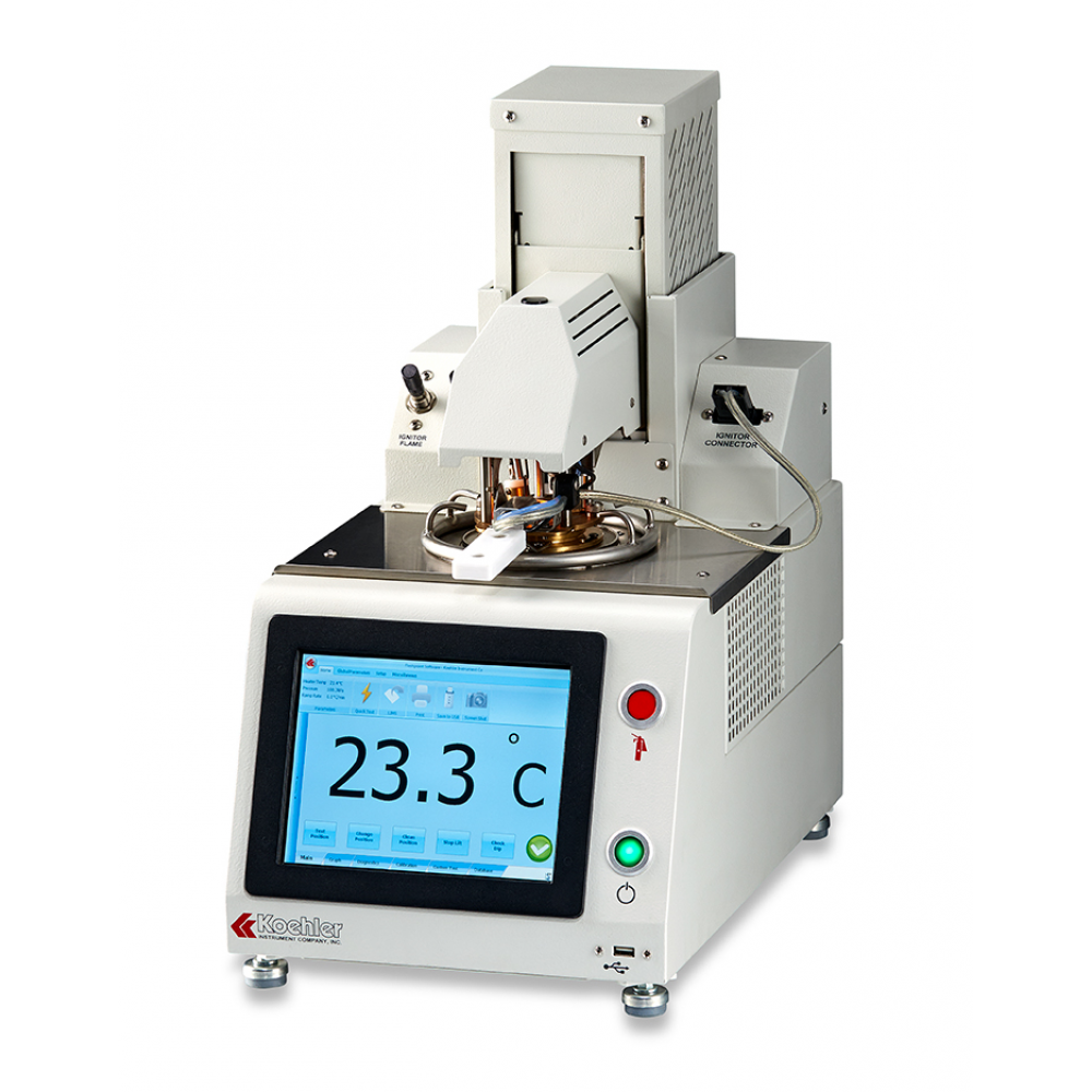
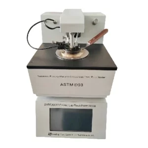
Basics of Pensky-Martens closed-cup flash point testing

The flash point is essentially the lowest temperature of the liquid or semi-solid at which vapors from a test portion combine with air to give a flammable mixture and “flash” when an ignition source is applied. Flash point testing is required in the petroleum industry to characterize fuels and petroleum-based products as part of quality control and to meet safety regulations concerning the transport of these products. 

Development and history of flash point testing

The discovery of petroleum and the increased use of flammable distillates in the 19th century for lighting and heating in place of animal and vegetable oils led to a large number of explosions and other fire-related accidents.

Legislation, such as the UK Petroleum Act in 1862 and the German Petroleum Regulations in 1882, quickly spread around the world and led to the development of many types of test instruments. The following list shows the dates when the major surviving instruments were in a form more or less recognizable today:

1870 – 1880 Abel closed cup, Pensky-Martens closed cup
1910 – 1920 Tag closed cup, Cleveland open cup

The Pensky-Martens Flash Point Tester was developed in Germany in 1870 by Mr. Martens and was based on the original tester by Mr. Pensky. Its development in 1870 was for flash points well above 100 °C to test lubricating oils and other similar products such as bitumen products.

During the last century the manual Pensky-Martens Closed Cup Tester was improved to make it a fully automatic instrument.

Instrument timeline
Fig. 2: Timeline of the development from manual to automatic instrument

Why measure the flash point using the Pensky-Martens closed cup tester?

The flash point is defined as the lowest temperature of a liquid or semi-solid at which vapors from a test portion combine with air to give a flammable mixture and then “flash” when an ignition source is applied.

The Pensky-Martens Flash Point Tester consists of a closed-cup test arrangement that contains any vapors produced and essentially simulates the situation in which a potential source of ignition is accidentally introduced into a container. For this test, a test portion is introduced into a cup and a close-fitting lid is fitted to the top of the cup. The cup and test portion are heated and stirred, apertures are then opened in the lid to allow air into the cup and also the ignition source to be dipped into the vapors to test for a flash.

The closed-cup test like the Pensky-Martens predominates in product specification and regulations due to its greater precision and its ability to detect contaminants.

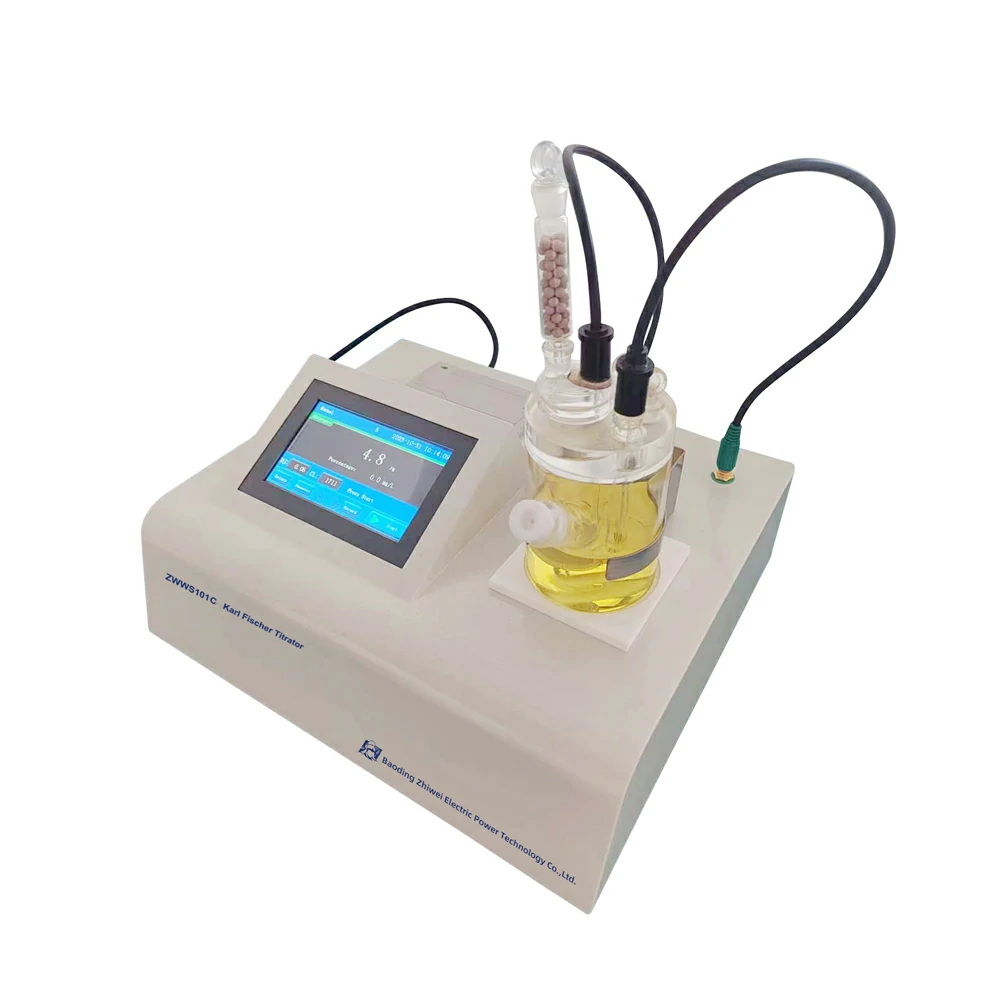
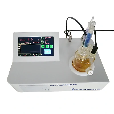
How does the coulometric kf titrator of samples with low conductivity?

When using a coulometric Karl Fischer (KF) titrator for samples with low conductivity, special considerations and techniques are necessary to ensure accurate and reliable moisture determination.

Here’s how the coulometric KF titrator handles samples with low conductivity:

  1. Optimization of Electrolysis Parameters: Coulometric KF titrators rely on the principle of electrochemical coulometry to generate iodine for the titration reaction. For samples with low conductivity, the electrolysis parameters, such as the current density and electrolysis time, may need to be optimized to ensure sufficient iodine generation for the titration reaction. Adjustments to these parameters can be made based on the sample’s conductivity and moisture content to achieve accurate results.
  2. Use of Proper Electrolyte Solution: The choice of electrolyte solution is crucial for ensuring efficient electrolysis and accurate titration in coulometric KF titration. For samples with low conductivity, selecting an appropriate electrolyte solution with high conductivity and compatibility with the sample matrix is essential. Commonly used electrolyte solutions include methanol-based or ethanol-based solutions, which help enhance the conductivity of the sample and facilitate the titration process.
  3. Sample Pre-treatment: Samples with low conductivity may require pre-treatment techniques to improve their conductivity and enhance the accuracy of moisture determination. This could involve dilution with a suitable solvent, homogenization, coulometric kf titrator or addition of conductivity-enhancing additives to the sample. Care should be taken to ensure that the pre-treatment method does not introduce moisture or interfere with the titration reaction.
  4. Optimization of Titration Parameters: In addition to electrolysis parameters, other titration parameters, such as the titrant concentration, titration speed, and endpoint detection method, may need to be optimized for samples with low conductivity. Fine-tuning these parameters based on the sample’s characteristics can help improve the accuracy and precision of moisture determination in coulometric KF titration.
  5. Calibration and Validation: Regular calibration and validation of the coulometric KF titrator are essential to ensure accurate and reliable moisture determination, especially when analyzing samples with low conductivity. Calibration standards and validation protocols should be established and followed to verify the performance of the instrument and ensure the validity of the results.

By implementing these techniques and precautions, the coulometric KF titrator can effectively handle samples with low conductivity and provide accurate moisture determination in various applications. Close attention to sample preparation, titration parameters, and instrument calibration is essential to achieve reliable results in coulometric KF titration.

How does the viscosity test equipment replenishment?

Replenishing viscosity test equipment typically involves adding or replacing the testing fluid or oil used in the viscometer.

Here’s a general overview of how replenishment is typically carried out:

  1. Selection of Testing Fluid: The first step is to select the appropriate testing fluid or oil for the viscometer based on the type of viscosity measurement being performed and the specifications of the instrument. The viscosity of the testing fluid should cover the expected range of viscosity values for the samples being tested.
  2. Preparation of Testing Fluid: If using a new batch of testing fluid, it may need to be prepared according to manufacturer instructions. This could involve mixing or diluting the fluid with specific solvents or additives to achieve the desired viscosity and ensure compatibility with the viscometer.
  3. Draining Old Fluid: If the viscometer currently contains old or used testing fluid, it needs to be drained or flushed out of the instrument. This is typically done by opening valves or ports on the viscometer to allow the fluid to flow out into a waste container.
  4. Cleaning and Maintenance: Before replenishing with new testing fluid, it’s important to clean the viscometer thoroughly to remove any residue or contaminants from the previous testing fluid. This may involve flushing the instrument with a solvent or cleaning solution and wiping down internal components.
  5. Refilling with New Fluid: Once the viscometer is clean and prepared, the new testing fluid can be replenished. viscosity test equipmentThis is typically done by pouring or injecting the fluid into the viscometer through designated filling ports or openings. Care should be taken to avoid introducing air bubbles or contaminants into the fluid during replenishment.
  6. Calibration and Verification: After replenishing the testing fluid, it’s important to calibrate and verify the performance of the viscometer to ensure accurate and reliable viscosity measurements. This may involve running calibration standards or reference samples through the instrument and comparing the results to established benchmarks.
  7. Regular Maintenance: To maintain the performance of the viscosity test equipment, it’s essential to follow a regular maintenance schedule, including periodic cleaning, calibration, and fluid replenishment. This helps ensure the accuracy and reliability of viscosity measurements over time.

By following these steps, viscosity test equipment can be replenished with new testing fluid effectively, ensuring accurate and reliable viscosity measurements in various applications.

What are the reporting capabilities of an ground resistance tester?

Ground resistance testers, also known as earth resistance testers or ground impedance testers, are used to measure the resistance of the grounding system or earth electrode of electrical installations. These testers typically provide various reporting capabilities to document and analyze measurement results effectively.

Here are some common reporting capabilities of ground resistance testers:

  1. Measurement Results: Ground resistance testers display the measured resistance values directly on their built-in screens or digital displays. These measurements may include resistance values for each individual electrode or grounding point, as well as overall resistance values for the entire grounding system.
  2. Data Logging: Many modern ground resistance testers feature data logging capabilities, allowing users to record and store measurement data over time. These testers can store multiple measurement records, along with corresponding timestamps, measurement parameters, and location information, facilitating trend analysis and historical tracking of grounding system performance.
  3. Report Generation: Ground resistance testers may support the generation of comprehensive test reports summarizing measurement results and analysis. Users can customize report templates, add annotations or comments, and include relevant information such as test conditions, equipment used, and environmental factors. Some testers offer built-in report generation features, while others may require external software for report creation.
  4. Graphical Representation: Ground resistance testers may provide graphical representations of measurement data, such as line graphs or bar charts, to visualize variations in resistance values across different electrodes or measurement points. Graphical analysis can help identify trends, anomalies, or areas requiring further investigation within the grounding system.
  5. Data Transfer: Ground resistance testers often support data transfer capabilities, allowing users to export measurement data to external devices or software applications for further analysis and processing. Common data transfer methods include USB, Bluetooth, Wi-Fi, or SD card connectivity, enabling seamless integration with data management systems and reporting tools.
  6. Alarm and Alert Functions: Some ground resistance testers incorporate alarm and alert functions to notify users of measurement anomalies or out-of-specification conditions. These testers may trigger visual or audible alarms, display warning messages, or highlight abnormal measurement values, prompting users to take corrective actions or conduct follow-up inspections.
  7. Compliance Documentation: Ground resistance testers may assist users in documenting compliance with relevant industry standards, regulations, or safety requirements. Testers may include pre-programmed test protocols or measurement procedures based on applicable standards (e.g., IEEE, IEC), helping users ensure adherence to best practices and regulatory guidelines.

Overall, ground resistance testers offer a range of reporting capabilities to facilitate accurate measurement, analysis, and documentation of grounding system performance. These reporting features enhance data management, troubleshooting, and maintenance efforts, supporting the safe and reliable operation of electrical installations.

What are the diagnostic capabilities of an karl fischer coulometric titration for detecting machinery faults?

Karl Fischer (KF) coulometric titration is a widely used method for determining the water content in various substances, including oils, solvents, and chemicals. While KF titration itself is not specifically designed for diagnosing machinery faults, it can provide valuable diagnostic insights when applied in the context of condition monitoring and maintenance of machinery.

Here are some diagnostic capabilities of KF coulometric titration for detecting machinery faults:

  1. Detection of Water Contamination: One of the primary applications of KF titration is to detect water contamination in oils and lubricants used in machinery. Excessive water content in lubricating oils can lead to accelerated wear, corrosion, and degradation of machinery components. KF titration can identify changes in water content over time, indicating potential leaks, seal failures, or ingress of water into the machinery system.
  2. Monitoring Lubricant Degradation: Water content in oils and lubricants can accelerate the degradation of lubricant additives and base oils, leading to reduced lubricating properties and increased friction and wear. By measuring water content with KF titration, maintenance personnel can monitor the degradation of lubricants and assess their effectiveness in protecting machinery components against wear and corrosion.
  3. Identification of Oil Oxidation: Water content in oils can promote oxidation and degradation of oil molecules, leading to the formation of acidic by-products and increased acidity levels in the oil. KF titration can detect changes in water content and acidity levels, providing indications of oil oxidation and degradation. karl fischer coulometric titration High acidity levels may indicate the presence of acidic contaminants or degradation products, which can contribute to machinery faults and performance issues.
  4. Assessment of Seal Integrity: Seals and gaskets are critical components in machinery systems, preventing the ingress of contaminants, including water, into sensitive components such as bearings and gears. Changes in water content measured by KF titration can indicate seal failures or breaches in the machinery enclosure, allowing maintenance personnel to identify and address potential sources of water contamination.
  5. Predictive Maintenance Insights: By monitoring water content and trends over time using KF titration, maintenance personnel can gain insights into the condition of machinery components and predict potential failure modes. Sudden increases in water content or deviations from established baselines may signal impending machinery faults, prompting proactive maintenance actions to prevent downtime and costly repairs.

While KF coulometric titration is primarily used for quantifying water content in oils and lubricants, its diagnostic capabilities extend beyond simple moisture measurement. When integrated into a comprehensive condition monitoring program, KF titration can provide valuable insights into machinery health, lubricant condition, and potential failure modes, supporting proactive maintenance strategies and ensuring the reliability and performance of industrial equipment.

How does an electrical test meter handle oil samples with additives or modifiers?

Electrical test meters, such as multimeters or insulation resistance testers, are primarily designed to measure electrical parameters and assess the condition of electrical components, systems, and insulation. While these meters are not typically used to directly handle or analyze oil samples with additives or modifiers, the presence of additives or modifiers in oil-filled equipment can indirectly impact electrical testing in several ways:

  1. Dielectric Properties: Additives or modifiers in oil can alter the dielectric properties, such as permittivity, dissipation factor, and breakdown voltage, of the oil-insulated components. Electrical test meters may detect variations in these properties during insulation resistance testing or dielectric strength testing, providing insights into the condition of the insulation system.
  2. Insulation Resistance Testing: Insulation resistance testers are used to assess the integrity of electrical insulation by measuring the resistance between conductive surfaces and ground. Additives or modifiers in oil can affect the insulation resistance readings by influencing the conductivity or resistivity of the oil-insulated components. Electrical test meters may detect deviations from expected resistance values, indicating potential issues with insulation integrity.
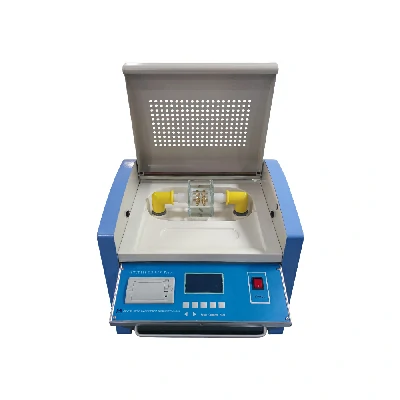
  3. Dielectric Strength Testing: Dielectric strength testers evaluate the ability of insulation materials, including oil, to withstand electrical stress without breakdown. Additives or modifiers in oil may affect the breakdown voltage or withstand voltage of the insulation, impacting the results obtained during dielectric strength testing. electrical test meter Electrical test meters may detect anomalies in voltage levels or breakdown behavior, indicating variations in oil quality or composition.
  4. Temperature Compensation: Some electrical test meters incorporate temperature compensation features to account for variations in ambient temperature during testing. Additives or modifiers in oil can influence the thermal conductivity or heat dissipation properties of the oil-insulated components, affecting temperature-dependent measurements obtained with electrical test meters.
  5. Calibration Considerations: Electrical test meters used for oil-filled equipment testing may require calibration adjustments or corrections to account for the presence of additives or modifiers in the oil. Calibration procedures ensure the accuracy and reliability of test meter measurements and help mitigate the impact of oil-related factors on testing results.

Overall, while electrical test meters are not specifically designed to handle oil samples with additives or modifiers, they can indirectly assess the condition of oil-insulated components by measuring electrical parameters and detecting variations in insulation properties. Proper interpretation of test meter readings, consideration of oil-related factors, and adherence to relevant standards and procedures are essential for accurate and reliable electrical testing of oil-filled equipment.

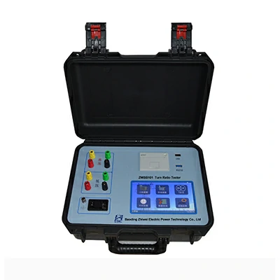
How should the operator respond to unexpected or abnormal behavior from the ttr tester?

When faced with unexpected or abnormal behavior from the TTR (Transformer Turns Ratio) tester, operators should follow these steps to ensure safety and proper troubleshooting:

  1. Cease Testing: Immediately stop testing if you notice any unexpected or abnormal behavior from the TTR tester. Ceasing testing is crucial to prevent potential damage to equipment or injury to personnel.
  2. Isolate the Tester: Turn off the TTR tester and disconnect it from the power source. Ensure that all connections to the transformer or test object are also disconnected to prevent any electrical hazards.
  3. Assess the Situation: Evaluate the nature of the unexpected behavior. This may include unusual readings, abnormal sounds, smoke, sparks, or physical damage to the tester or equipment.
  4. Refer to the Manual: Consult the user manual or manufacturer’s documentation for troubleshooting guidance. The manual may contain specific instructions for addressing common issues or abnormal behavior encountered with the TTR tester.
  5. Check Connections: Verify that all connections to the transformer terminals and test leads are secure and properly seated. Loose or faulty connections can result in inaccurate readings or erratic behavior.
  6. Inspect Test Leads: Examine the test leads for any signs of damage, wear, or fraying. Damaged test leads can compromise the accuracy of measurements and pose a safety risk.
  7. Perform Self-Test: If the TTR tester has a built-in self-test function, use it to check the functionality and calibration of the device. ttr tester Follow the manufacturer’s instructions for conducting a self-test and interpreting the results.
  8. Calibration Check: Verify the calibration of the TTR tester to ensure accurate measurements. Some abnormal behavior may be due to calibration drift or inaccuracies in the instrument.
  9. Contact Manufacturer Support: If troubleshooting steps do not resolve the issue or if the abnormal behavior persists, contact the manufacturer’s technical support or customer service for assistance. Provide detailed information about the symptoms and any troubleshooting steps taken.
  10. Document the Issue: Keep a record of the unexpected behavior encountered with the TTR tester, including the symptoms observed, troubleshooting steps taken, and any communication with the manufacturer or technical support team.
  11. Implement Safety Measures: Ensure that appropriate safety precautions are followed throughout the troubleshooting process to protect personnel and equipment from potential hazards.
  12. Professional Inspection: If the issue cannot be resolved through troubleshooting or if there are concerns about the safety or functionality of the TTR tester, consider seeking assistance from a qualified technician or professional for further inspection and repair.

By following these steps, operators can effectively respond to unexpected or abnormal behavior from the TTR tester, identify potential issues, and take appropriate actions to ensure safety and reliable testing operations.

How should the operator protect themselves from arc flash hazards when using the vlf ac hipot tester?

When using a VLF AC hipot tester, operators should take precautions to protect themselves from arc flash hazards, which can occur due to high voltage and current levels.

Here are some essential safety measures:

  1. Wear Personal Protective Equipment (PPE):
    • Arc-rated clothing: Wear arc-rated clothing that covers the entire body, including flame-resistant shirts, pants, coveralls, and jackets made from materials designed to withstand arc flash hazards.
    • Insulated gloves: Use insulated gloves rated for the voltage levels being tested to protect against electric shock and burns.
    • Safety glasses or face shield: Wear safety glasses with side shields or a face shield to protect the eyes from arc flash debris or projectiles.
    • Arc-rated head protection: Wear an arc-rated hard hat to protect against head injuries from falling objects or arc flash hazards.
    • Arc-rated footwear: Wear arc-rated footwear with non-conductive soles to protect against electric shock and burns.
  2. Maintain Safe Distances:
    • Keep a safe distance from the testing area and ensure that bystanders are also at a safe distance to minimize the risk of injury from arc flash hazards.
    • Follow the manufacturer’s recommendations for minimum approach distances when working near energized equipment or conductors.
  3. Use Insulated Tools:
    • Use insulated tools and equipment designed for electrical work to prevent accidental contact with energized components and reduce the risk of arc flash hazards.
  4. Follow Lockout/Tagout Procedures:
    • Implement lockout/tagout procedures to de-energize and isolate the equipment being tested before performing maintenance or testing to prevent accidental energization and arc flash hazards.
  5. Perform Risk Assessments:
    • Conduct a thorough risk assessment of the testing environment to identify potential arc flash hazards and implement appropriate control measures to mitigate risks.
  6. Follow Safe Work Practices:
    • Adhere to safe work practices and procedures when operating the VLF AC hipot tester, including proper equipment setup, vlf ac hipot tester test procedures, and emergency response protocols.
    • Ensure that all personnel involved in testing operations are trained in electrical safety practices and aware of the risks associated with arc flash hazards.
  7. Use Remote Operation:
    • Whenever possible, use remote operation features or control panels to minimize direct exposure to high voltage and reduce the risk of arc flash hazards.
  8. Emergency Response Preparedness:
    • Establish and communicate emergency response procedures for dealing with arc flash incidents, including first aid, evacuation, and notification protocols.

By following these precautions and safety measures, operators can protect themselves from arc flash hazards when using a VLF AC hipot tester and ensure a safe testing environment for themselves and others involved in testing operations.

How are government policies and regulations shaping TCM Formula Granule production and processing?

Government policies and regulations play a crucial role in shaping Traditional Chinese Medicine (TCM) Formula Granule production and processing in several ways:

  1. Quality Standards: Government agencies establish and enforce quality standards and specifications for TCM Formula Granules to ensure product safety, efficacy, and consistency. These standards cover various aspects of production and processing, including raw material sourcing, manufacturing practices, quality control, and labeling requirements. Compliance with quality standards is essential for TCM Formula Granule manufacturers to obtain regulatory approvals and market their products legally.
  2. Good Manufacturing Practices (GMP): Governments may require TCM Formula Granule manufacturers to adhere to Good Manufacturing Practices (GMP) regulations, which set forth guidelines for the design, construction, operation, and maintenance of manufacturing facilities, as well as procedures for quality control, personnel training, documentation, and record-keeping. GMP compliance helps ensure that TCM products are produced under hygienic conditions and meet quality and safety standards.
  3. Regulatory Approval Process: Government regulatory agencies oversee the approval and registration of TCM Formula Granules for commercial sale. Manufacturers must submit comprehensive documentation, including evidence of product safety, efficacy, quality, and manufacturing compliance, to regulatory authorities for review and approval. The regulatory approval process typically involves rigorous evaluation of product formulation, manufacturing processes, stability data, toxicology studies, and clinical trials, if applicable.
  4. Ingredient Regulation: Government regulations govern the sourcing, identification, authentication, and quality control of raw materials used in TCM Formula Granules. Authorities may establish lists of approved botanical ingredients, herbal extracts, and other TCM components, along with specifications for purity, potency, and contaminants limits. China TCM Formula Granule suppliers Manufacturers must ensure that their raw material suppliers comply with regulatory requirements and provide documentation to verify the authenticity and quality of ingredients.
  5. Safety and Toxicity Assessment: Government agencies evaluate the safety and toxicity of TCM Formula Granules to protect public health and prevent adverse reactions or harm. Toxicological studies, including acute toxicity, genotoxicity, and long-term toxicity tests, may be required to assess the safety profile of TCM products. Manufacturers must demonstrate the safety of their products through preclinical testing and risk assessment to obtain regulatory approval for commercialization.
  6. Labeling and Packaging Regulations: Government regulations dictate labeling and packaging requirements for TCM Formula Granules to ensure accurate product identification, information disclosure, and consumer protection. Labels must contain essential information such as product name, ingredients, dosage instructions, warnings, expiration date, batch number, and manufacturer’s contact information. Packaging materials must be safe, tamper-evident, and appropriately labeled to prevent contamination and ensure product integrity.
  7. Post-Market Surveillance: Government regulatory agencies conduct post-market surveillance and monitoring of TCM Formula Granules to detect and respond to adverse events, product quality issues, and safety concerns. Manufacturers are required to report adverse reactions, product complaints, and quality deviations to regulatory authorities promptly. Authorities may take enforcement actions, such as product recalls, market withdrawals, or sanctions, against non-compliant manufacturers to protect public health and safety.

Overall, government policies and regulations play a critical role in shaping TCM Formula Granule production and processing by establishing quality standards, GMP requirements, regulatory approval processes, ingredient regulations, safety assessments, labeling and packaging regulations, and post-market surveillance mechanisms. Compliance with regulatory requirements is essential for TCM manufacturers to ensure product quality, safety, and efficacy, gain market access, and maintain consumer trust and confidence in TCM products.